The Biquad below is based on instructions by MartyBugs (which is based on Trevor Marshall design). I've read several reports that people are using Biquads thats off-specifications and still works great, so I presume the design is relatively insensitive to smaller inaccuracies (but I recommend you follow them).
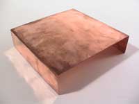
Cut the copper plate in 123.10 x 184.66 mm dimensions. The calculations for the dimensions:
| Width = Full wavelength = 123.10 mm Height = Full wavelength + (2 x 1/4 wavelength) = 123.10 + (2 x 30.78) = 184.66 mm |
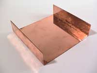
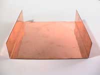
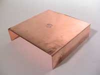
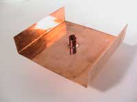
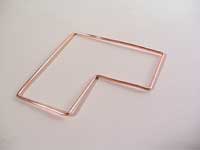
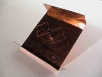
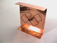
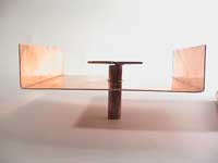
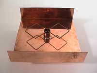
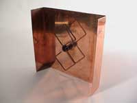
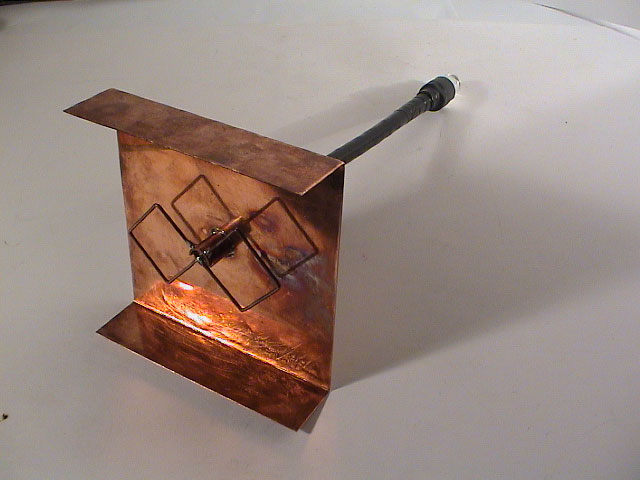
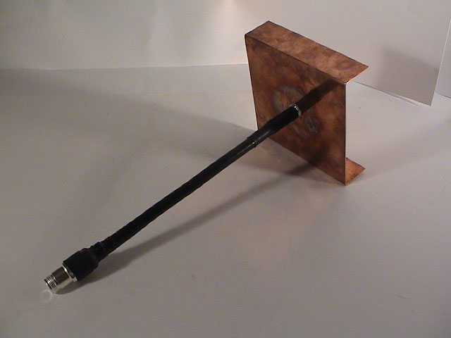
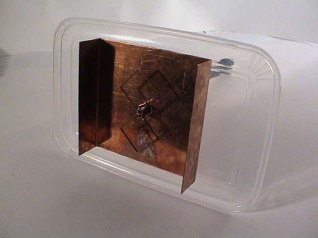
To limit the sidelobes (leakage of signal from the backplate) to the back of the Biquad, attach or bend two 'lips' on both sides of the reflector along the axis of the element to concentrate the radiation forward, as shown in the picture. [source 1] [source 2]
|
|
|
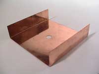
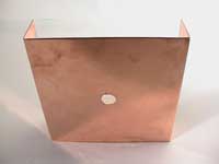
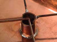
Drill a hole in the center of the plate. Measure from each corner to the opposite to find the center. Use a 12 mm drill piece, make sure it's fastened in the exact center to avoid vibrations.
 |
 |
 |
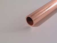
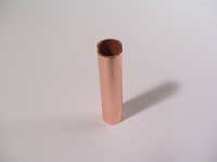
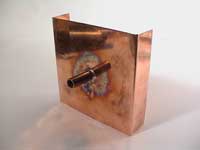
The pipe is used to attach the element and coax cable later on. The recommended length is 50 mm but could be anything above 18 mm (front distance + copper thickness).
It's important that the SWR (Standing Wave Ratio) is as low as possible so that the antenna is as efficient as possible. It's measured in relations to 1, a perfect impedance is 1:1. SWR is the amount of energy absorbed and radiated by an antenna compared to the amount it reflects back to the transmitter.
This table shows the element distance from the reflector and the SWR measured on channel 7 on a DWL-900AP:
| Distance | VSWR |
| 12.0 mm | 1 : 1.80 |
| 13.0 mm | 1 : 1.52 |
| 14.0 mm | 1 : 1.40 |
| 15.0 mm | 1 : 1.20 |
| 16.0 mm | 1 : 1.15 |
| 17.0 mm | 1 : 1.15 |
| 18.0 mm | 1 : 1.22 |
| 20.0 mm | 1 : 1.30 |
| 25.0 mm | 1 : 2.2 |
| 29.0 mm | 1 : 3.0 |
| 30.0 mm | 1 : 3.2 |
| 31.0 mm | 1 : 3.5 |
| 32.0 mm | 1 : 3.9 |
The most efficient element distance is 15-17 mm. By attaching the element's wire centre at 16 mm, will the lower part of the wire be just above 15 mm and the top be just under 17 mm. This should be optimal since the entire element is in the sweet spot between 15-17 mm.
The old, or first, SWR distance chart suggested 30.5 mm (1/4 wavelength), this was later ruled as wrong (see above).
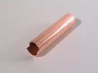
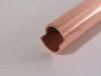
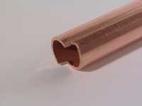
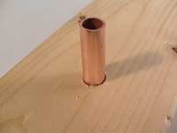
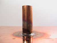
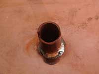
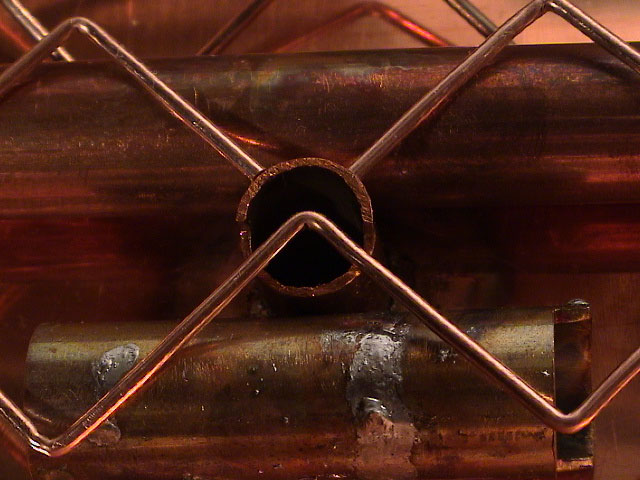
Cut off the notch before cutting the length of the short pipe. If you got a fairly long pipe, fasten it to a bench and use a saw to cut into the pipe 3 mm from the end and then remove the notch by cutting into the center of the pipe. Use some sandpaper to get it smooth and correct the dimensions.
It's also wise to roughen the point where the copper plate is supposed be attached so that the solder can more easily bind to the copper.
 |
 |
 |
 |
 |
|
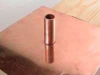
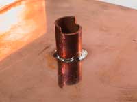
Soldering the pipe to the copperplate is the hardest part. Getting the correct front distance and temperature is tricky. I haven't used a electic solder iron but I bet it's not powerfull enough, instead I used a mini-gas soldering tool with a open flame. Use protective goggles whenever using soldering equipment.
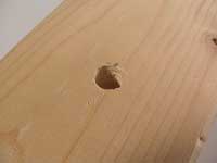
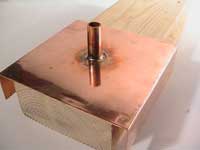
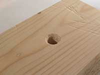
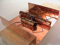
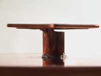
I created a stand to hold the pipe out of a wooden brick. This method made it much easier to position the pipe and soldering it to the copper plate. Just drill a hole that's as deep as the required front distance, 17 mm, and place the copperplate onto the pipe as shown.
 |
 |
 |
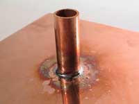
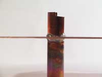
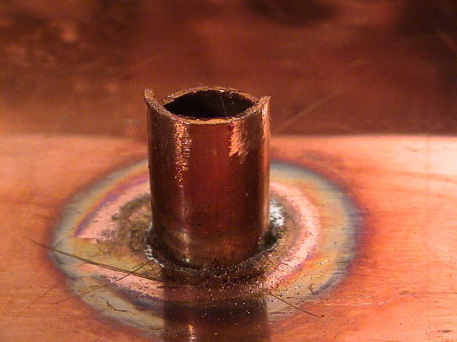
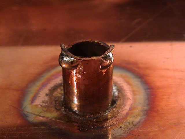
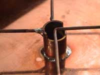
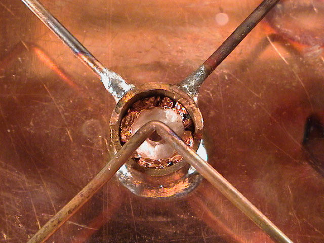
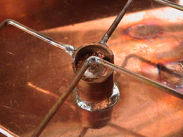
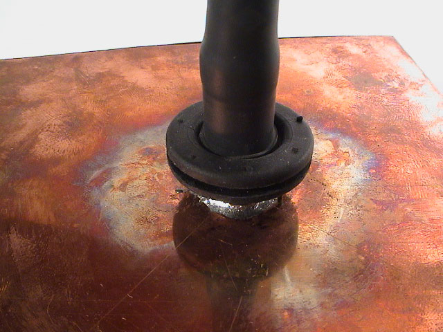
Warm the pipe and the plate for about a minute to get the correct temperature. Don't touch the plate or pipe, use tools instead. Feed the solder to the create a simuntanious joint around the entire pipe. When everything is covered, remove the heat and let it cool down for 2 minutes. Don't touch or move the copperplate, if you do you'll get a cold joint (which is bad).
 |
 |
 |
 |
 |
 |
 |
 |
|
Measure the front distance of the pipe and if it's correct, 17 mm, move on. If the distance is slightly wrong, over 1 mm, you should re-adjust it be repeating the above procedure.
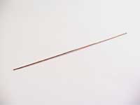
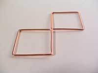
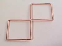
The element is attached to the top of the pipe and later to the conductor in the coax cable. The length of each element 'side', from wire centre to wire centre (corners), should be exactly 30.78 mm (quater wavelength = 123.10 / 4 = 30.78 mm).
The total wirelength should be 239 mm. This length is not important since the ends will be trimmed to fit the pipe later. Calculation:
| Wirelength = (1/4 wavelength x 8 sides) - ((wire thickness / 2) * 8 corners) = (30.78 x 8) - ((18 / 2) * 8) = 239,04 mm |
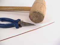
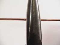
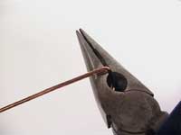
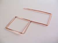
When bending the wire it's important that each corner, or bend, is pronounced and as close to 90 degrees as possible. I used a hammer to press the bend into a sharp corner of a plier to make it very pronounced.
 |
 |
 |
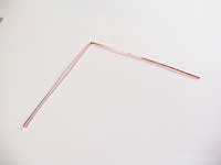
Find the center of the wire and bend it to 90 degrees, every bend will be 90 degrees from now on.
 |
 |
|
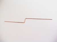
Then measure up 29.88 mm (Length = 1/4 wavelength - 1/2 wire thickness = 30.78 - 0.9) from the center of the first bend and mark the new bend point. Use the exact point find out where to set the plier and outer wire point to bend at.
Do this for the other part of the wire too.
 |
 |
|
Repeate the next bends as shown in the previous one.
 |
 |
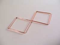 |
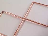
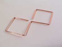
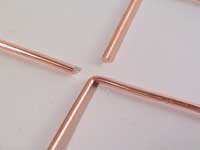
The ends in the final bend should just long enough to perfectly reach the first bend. If every bend is 90 degrees the two quads should be symmetrical.
 |
 |
 |
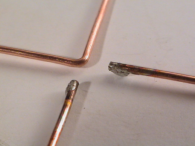
Now, take the element and hold it above the pipe end, mark the points where the wire ends needs to be cut off and trimmed so that it later can be attached to the pipe. Use a file to flatten the ends after you've cut them off.
After some calculations, I've found that you can measure the distance from the last bend and to the point where to cut.
| Distance = 1/4 wavelength - Outer radius of pipe = 30.78 - 6 = 24,78 mm |
 |
 |
|
Soldering the element to the pipe is easier than the first one. Just be caution to not heat the pipe and copperplate too much as this could melt the solder holding the pipe to the plate.
I made a second hold in the wooden brick so that it stood still. Make the hole 32 mm deep (Length = pipelength - front distance - plate thickness = 50 - 17 - 1). Use a file to make the opening a bit bigger for the solder to fit, you could do this for the first hole too for the solder that flowed through to the other side.
 |
||
Make the two spots rough with a file where the element is to be attached. Then heat the spots and tin the spots in addition to the wire ends, this makes it much easier to solder them together.
 |
 |
 |
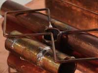
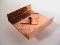
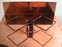
After fitting the reflector into the wooden brick, you'll have to find a way to position the element in a static way. I used some copperpipe ends I had lying around, the trickness is 15 mm which is perfect. When the element is held by the support pipes only the two ends should touch the upper part of the pipe, the other should be 1 mm above the lower edge of the pipe.
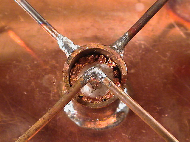
Heat the wire and the top of the pipe till the solder begins to melt and position the element in the center main axis of reflector. Wait a minte for the it to cool down. The joints should be continous and shiny.
 |
 |
 |
Remove the support pipes and wash the Biquad to remove flux and residue. The Biquad is now almost finished and you just have to attach the signal feed.
 |
 |
 |
 |
 |
 |
 |
 |
 |
 |
 |
|
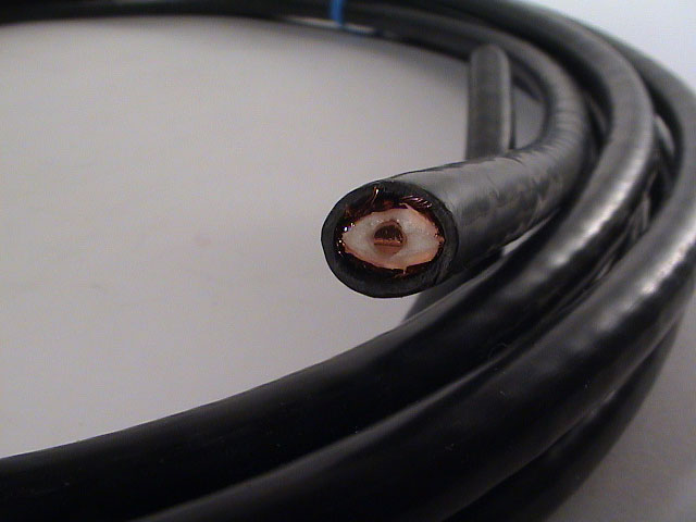
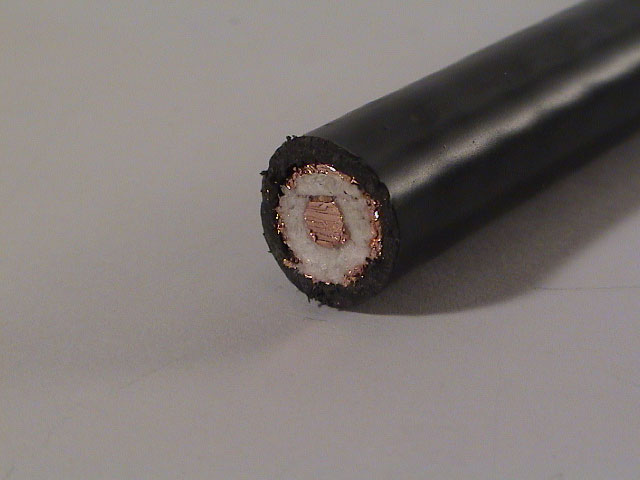
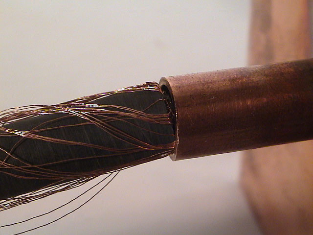
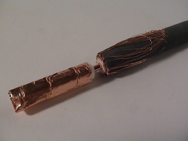
The coax cable needs to be as close the the inner diameter of the copper pipe. The ground shielding of the wire will be pressed against the inner of copper pipe so it's essential that the cable is close-fitting.
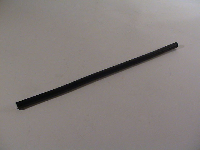
Let's prepare the antenna end of the cable. Cut a 30 cm length off the coax cable.
 |
 |
 |
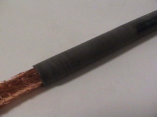
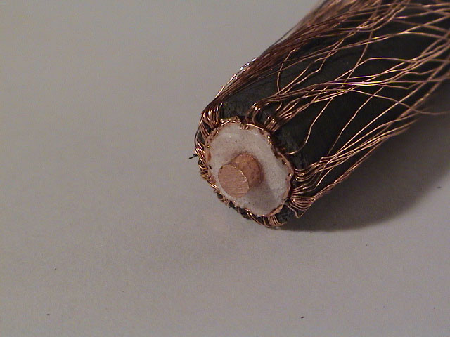
Remove about 30 mm of the outer plastic sheath. Try to fit the cable inside the copper pipe, if it fits nicely skip ahead. If it barely or doesn't fit at all you need to strip the plastic sheath untill it fits. I used sandpaper to prepare it. You only need to work on the frist 50 mm of the sheath, or the length of the copper pipe.
 |
 |
 |
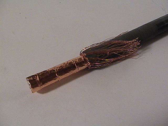
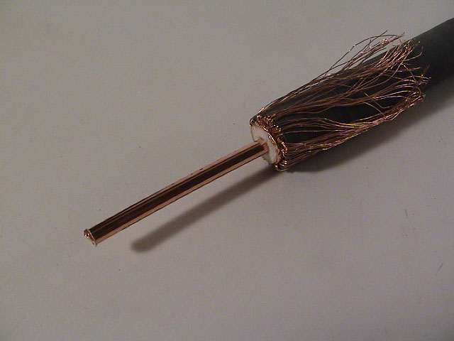
Remove the dielectric at the same point where the plastic sheath was cut, 30 mm. Cut the conductor 2 mm from the plastic sheath if the conductor is to be soldered under the antenna element or 4 mm if it's to be soldered to the side of it. I'm going to solder it under since it's more centre then on the side.
 |
 |
 |
 |
||
Align the inner conductor to the antenna element. The bottom of the element wire should be around 15 mm above the reflector, make sure the element is sitting nicely on top of the conductor when pressed down.
 |
 |
|
Remove the coax cable and tin the center of the element wire. Do the same on the conductor without heating or burning the dielectric or sheating too much, this makes it easier to solder them together.
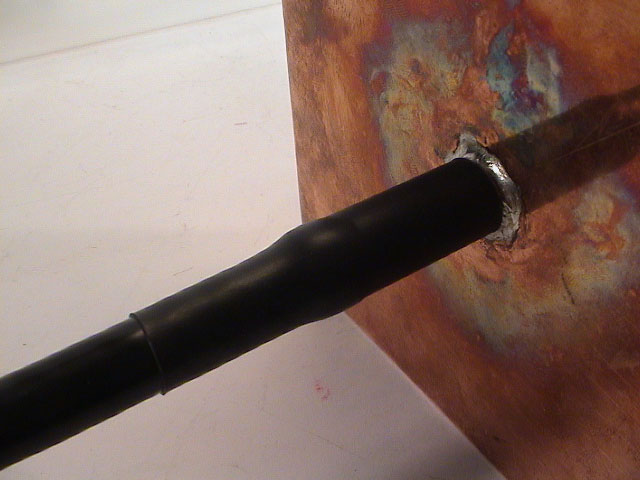
When soldering them together make sure you get a good electrical connection between the two. If one is colder than the other the solder won't "bind" to the copper and will only "float" above copper surface. Add a length of heat-shrinkable tubing on the back of the antenna to avoid water and dust expure.
 |
 |
 |
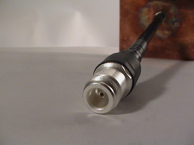
Attach a N female connector on the other end as shown on this page.
The antenna is almost finshed, only a enclosure is missing.
 |
 |
 |
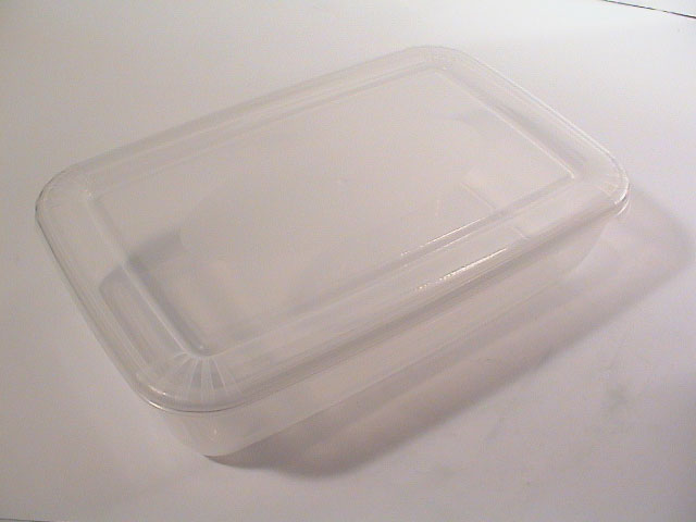
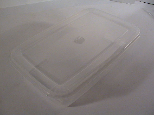
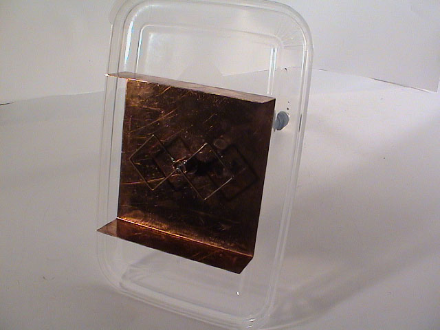
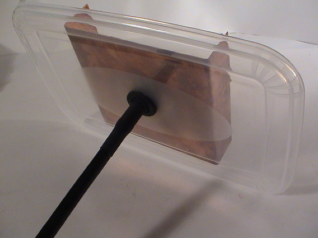
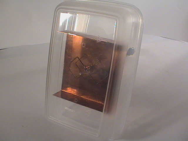
If you decied to use the antenna outside or want to protect the element from bending, find a fitting enclosure to put the antenna in. I found a box used for food preservation that worked fine.
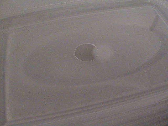
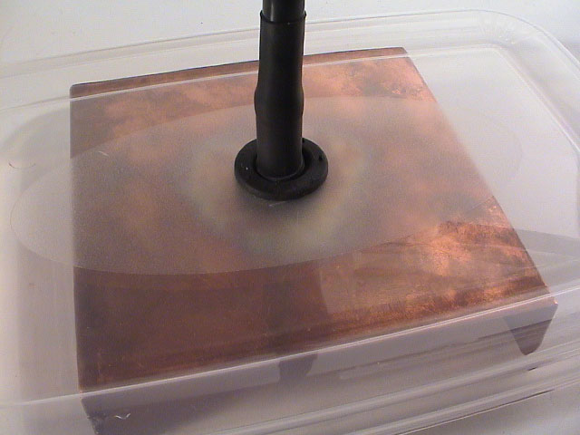
Bremel or drill a 20-22 mm hole on top of the enclosure for the cable. You could fit the enclosure before attaching the cable but I like to have the ability to remove or change the enclosure easily if it breaks or I find something better.
 |
 |
 |
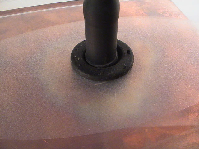
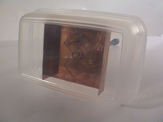
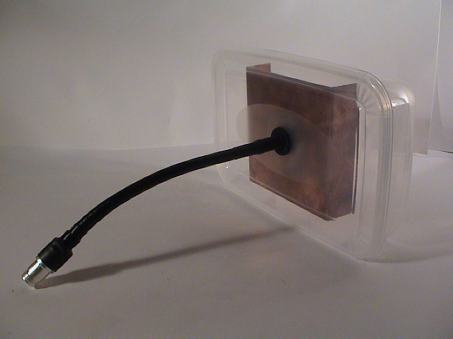
I had a grommet lying around from a previous project I could use to seal the opening.
 |
 |
 |
 |
 |
 |
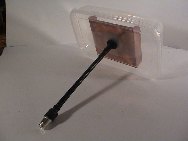
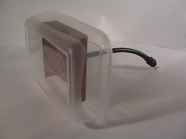
Finally, the antenna is finished and ready for use.
 |
 |
 |
 |
 |
|
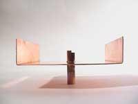
At first the polarization is probably different than you think it is. When the Biquad is standing on the side lips it's horizontal polarized, while it's vertical polarized when lying.
<pic>
<<>>
<martybugs azimuth plot pic>
A few variations exists, one without side lips, one with a smaller reflector for parabolic dishes, one with N socket connector instead of copper pipe or a variasion of all three.
Using this version you'll likely to pick up more noise coming from behind. The reflector can also be circular.
If the Biquad is to be mounted in a parabolic dish focus the reflector can be smaller and the need for side lips can be dropped.
This version is the least tuned one, since running a copper wire to the element and at the same time to the reflector introduces a new impedance. It's best to leave the feed inside a protected coax cable and solder it directly to the element, then no new impedance will interfere.
A double biquad is exactly what is says, double the element size and the reflector width. Tests by MartyBugs shows that the gain is 2 dBi higher compared to a single Biquad.
Biquad sites
List ordered by discovery and relation (for my own reference)
