This was my first attempt to connect two sites together using the 802.11g wifi technology. The first pare of the sites were located in the center of a fairly large town and about 40-50 meters apart, the second pare of connected sites were about 70-80 meters apart.
At first I though the distance was a long but after reading other stories this weren't long at all and a regular dipole antenna should be able to connect the site together, although the maximun speeds would probably be lower. Noise from other equipment could interfere with the network and I wanted a reliable link, so I decieded to go for a sector antenna for both sites. The setup consisted mostly of D-Link stock products; two access points, two antennas and a power-over-ethernet adaptor.
|
||
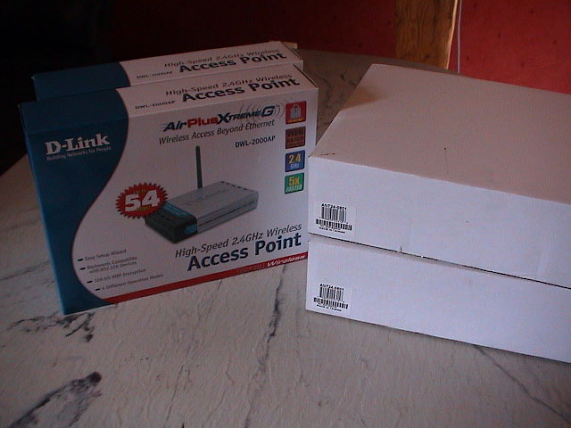
| 2x access points and antennas. |
Major parts:
Before I even could start the installation of the device and antenna, I had to get permission from the houselord for site B (new). I thought that making some 'cool' printed visuals would help but I didn't really need them because he had nothing against my little project. He only would like me to hide the cables as much as possible.
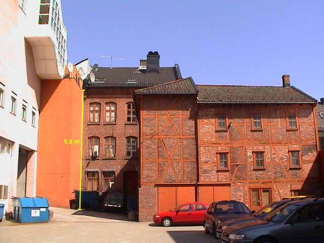
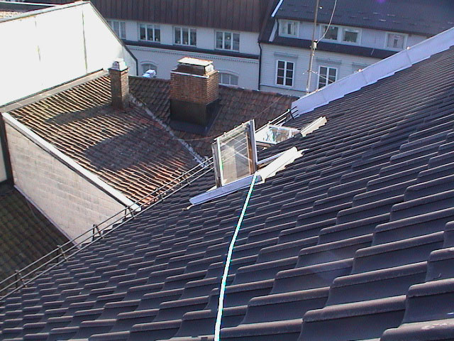
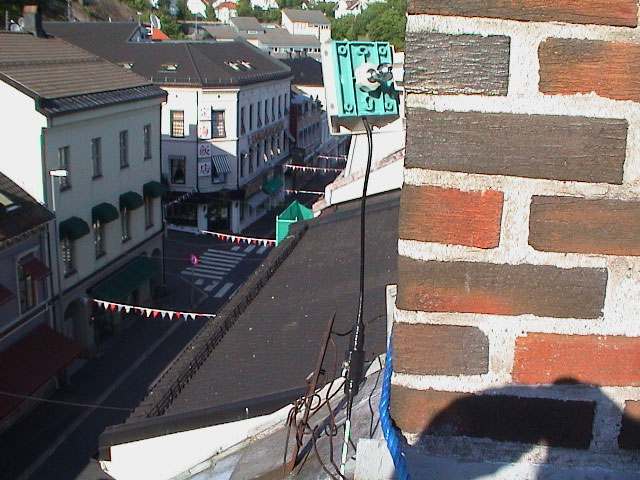
The pictures below are from the early planing and preparation and thus is somewhat outdated, i.e. the final location for the new site B is slightly moved and the old site B doesn't exists anymore.
 |
 |
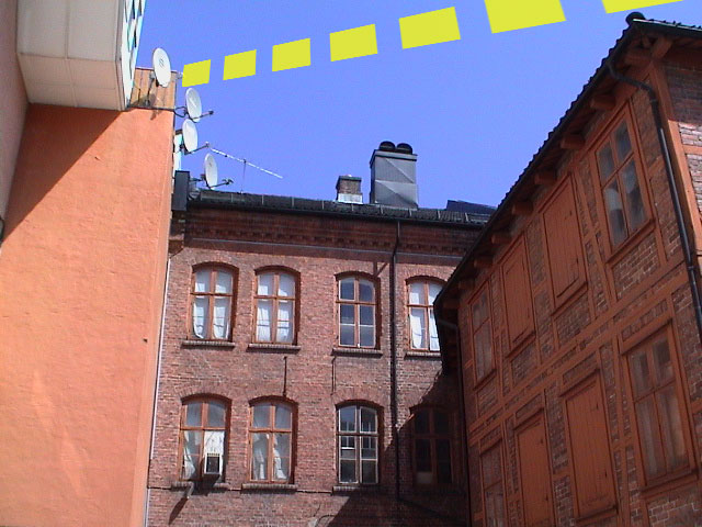
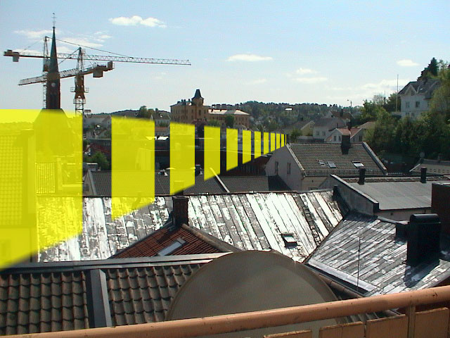 |
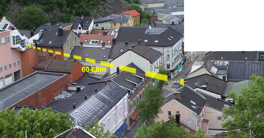
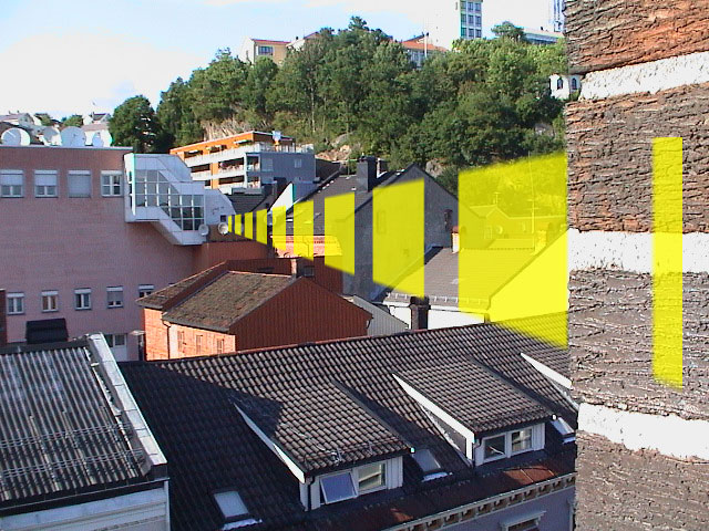
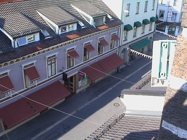
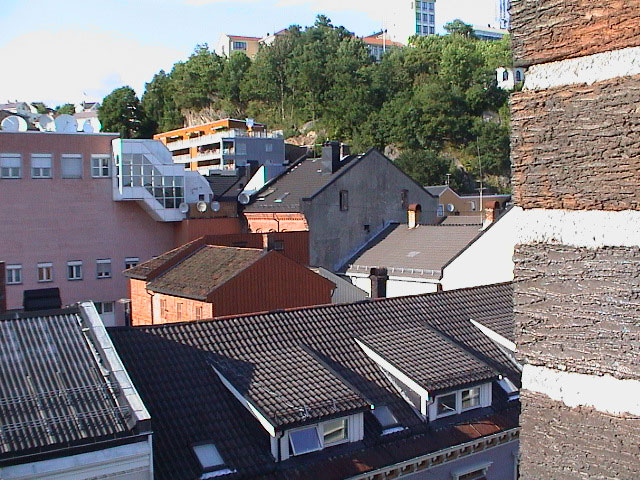
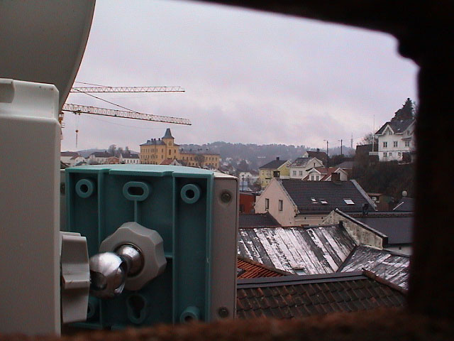
| Entire perspective over the locations. | View from site A to new site B. | View from new site B to site A. |
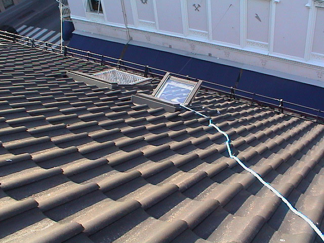
 |
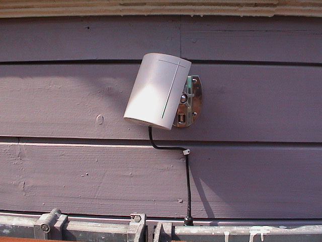 |
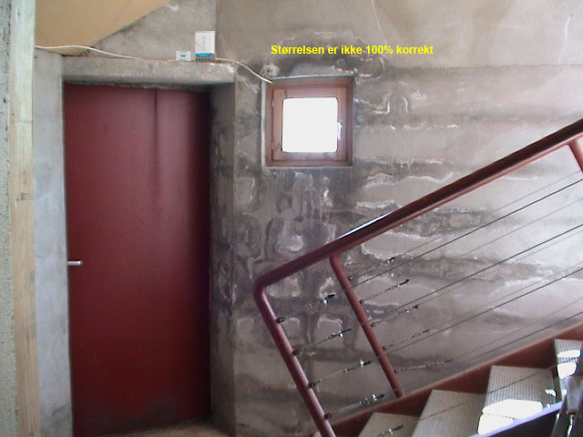
 |
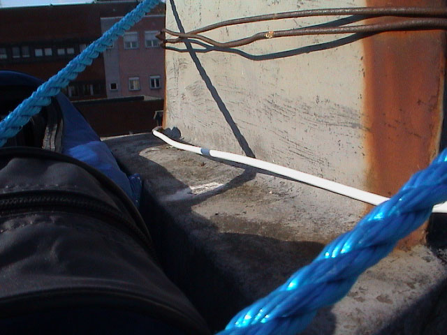
| Possible access point and PoE location. | Showing the size of the antenna. | Ground view of new site B. |
 |
 |
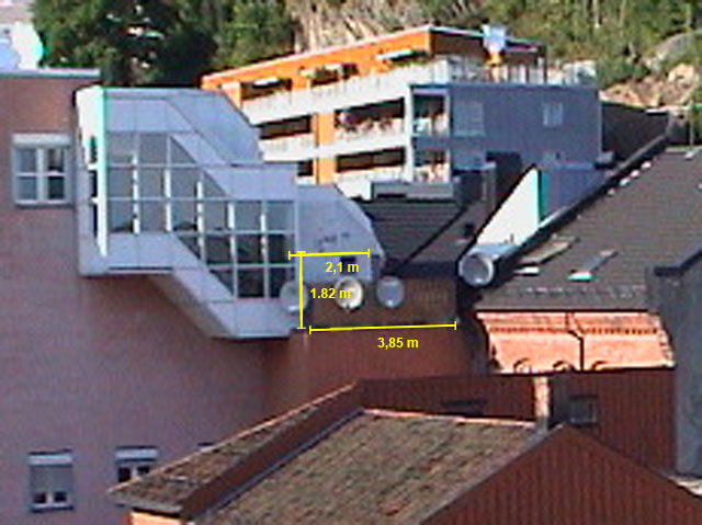
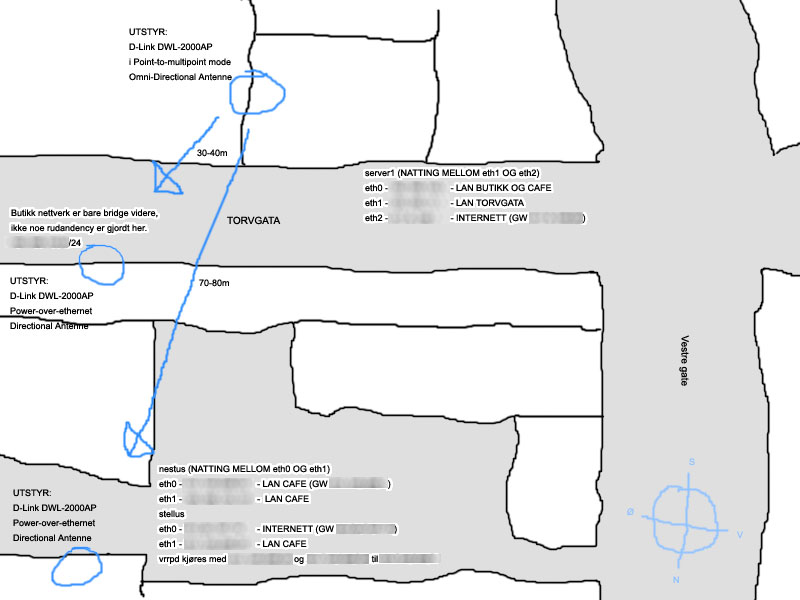 |
| Measurements used for cable length calculations. | More cable length calculations. | Sketch drawned in Photoshop. |
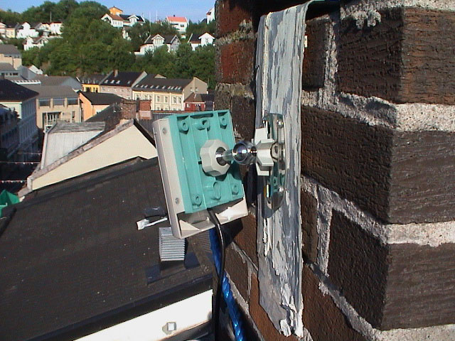
Site A is on top of an old 4 floor building. The access point is located just under the attic and the 3 meter antenna cable is just long enough to run up to the antenna. The antenna itself is attached to a aluminium sheet and put into the side of an unused chimney.
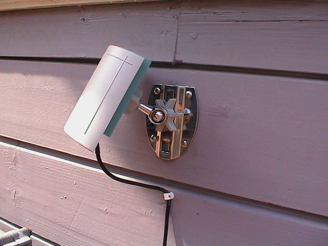
I found the aluminium sheet at a contruction site and bended it to the approx. dimensions, drilled holes for the mount and fastened it with the supplied screws. The swivel mount helps you to precisely position the antenna for maximum signal strength.
 |
 |
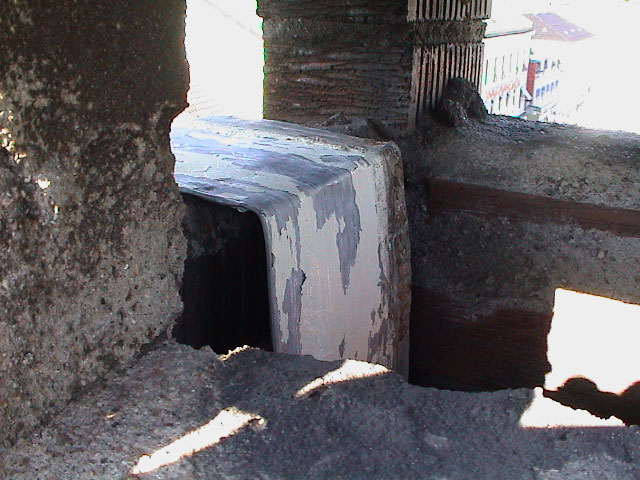 |
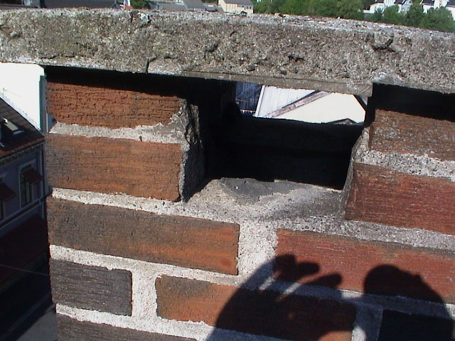
| Antenna mounted successfully. | The cap in the chimney is smaller than I thought. | Without knowing the thickness beforehan, I'm satisfied with mounting plate. |
 |
 |
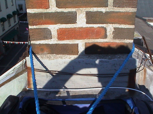 |
| Safty was improviced with thick ropes. | It worked well with ropes going to either side of the roof. | A final safety mecanism around the chimney. |
 |
 |
 |
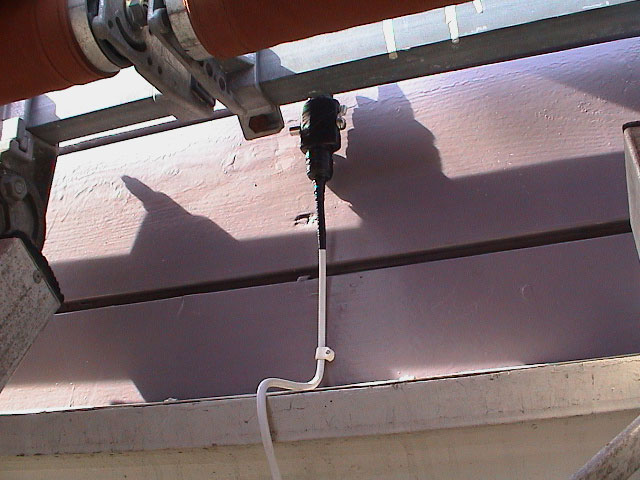
| The lightning surge protector not connected and is just haning down from the antenna. | This shows the old site B, you can see the other antenna in the center. | This is pointing to the direction of the future site B spot. |
 |
 |
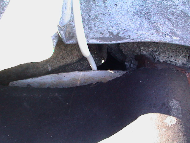 |
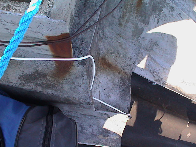
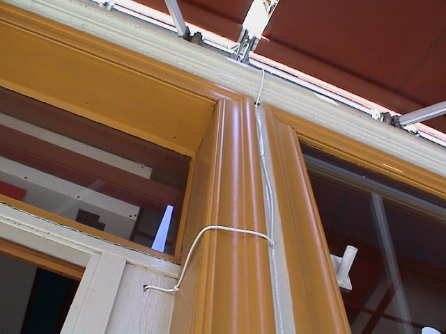
| Neatly stuffed around the edge. | The coax is going around the chimney to the other side. | And down a already present hole in the roof between the ceiling and the chimney. |
<to do, pics from ap inside>
Originally this site was used to hook up a small store with internet connection and a way to locally host a store website, but store went bankrupt a few months later. The coax cable included with the antenna was, luckly in this instance too, just long enough to reach the access point inside. The AP was not powered by PoE but rather by a longer extenstion power cable.
It put it up 3. August 2003 and later took it down in February 2004.
 |
 |
 |
| The antenna is pointing up towards the site A antenna. | The lightning surge protector is really not necessary in this location. | Afterwards I notice that I shouldn't have bent the coax that much. |
 |
 |
|
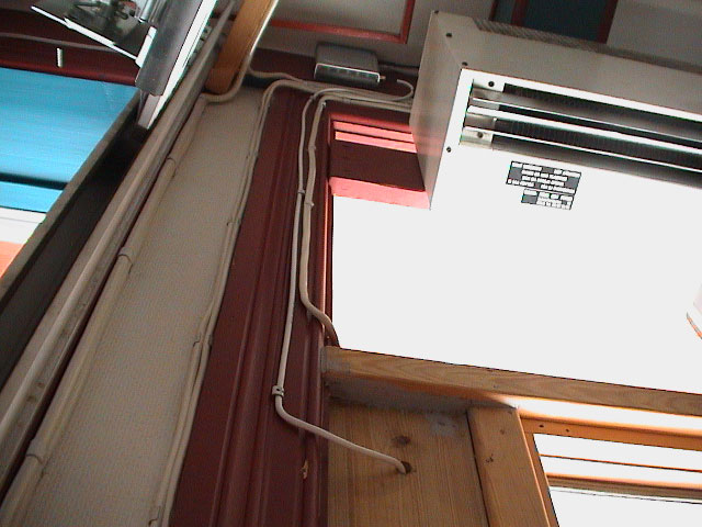
| Coming in and going up to the AP. | The is neatly placed up under the roof, the ethernet and power cable is connected over the coax connection. |
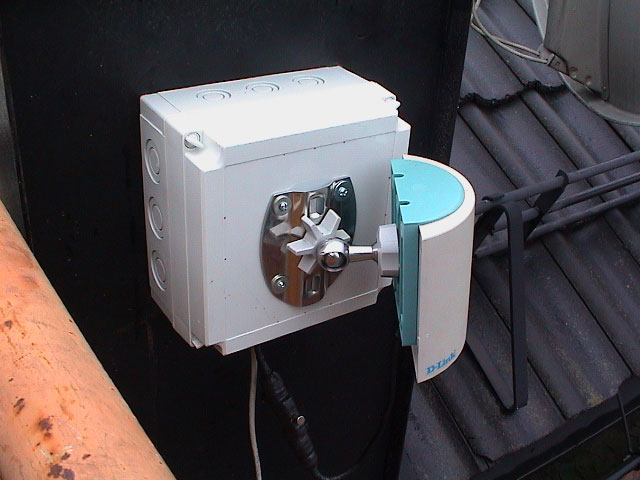
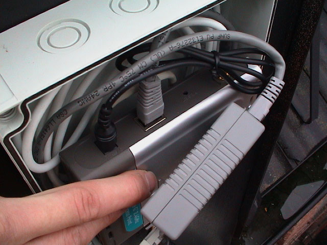
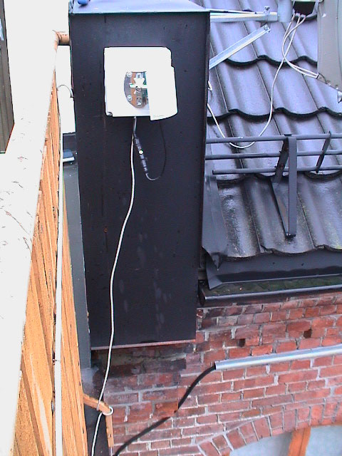
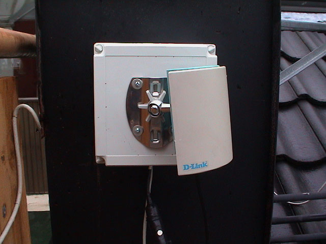
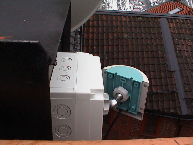
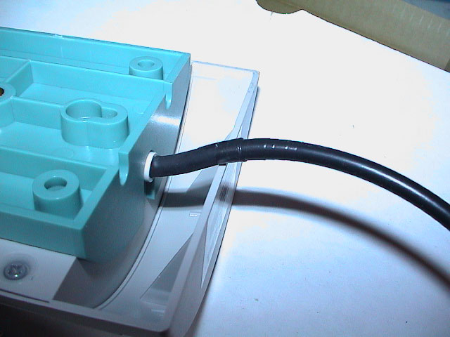
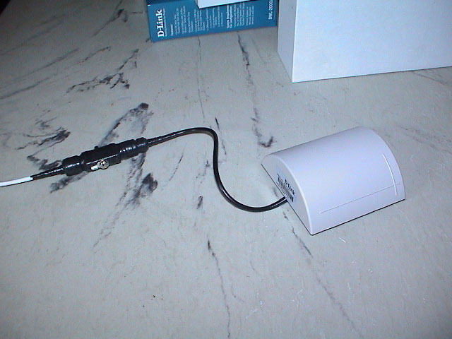
The new site B is located outside on a balcony near a few parabolic antennas. All the equipment is moved from the old site B. This the antenna is easier to reach than both site A and the old site B as it's attached to the front of a weatherproof box which contains everything. This makes this end of the link look very compact and professional.
The power is provided over D-Link's power-over-ethernet solution and the total distance between the terminators is around 15 meters. If the access point is locking up, it's easy to pull the plug in the other end to reset it.
The site went online 2. April 2004 and is still running strong as of 29. November 2004.
 |
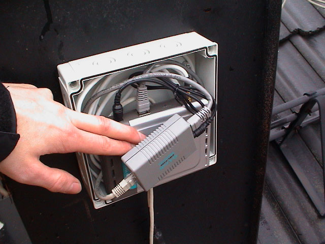 |
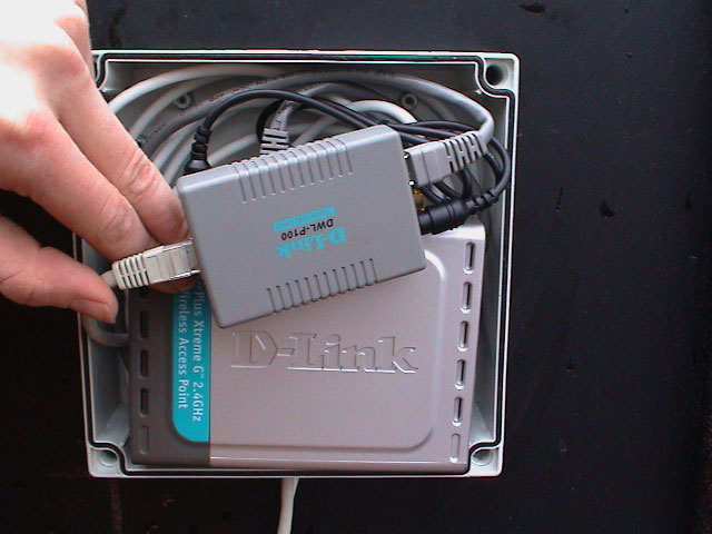
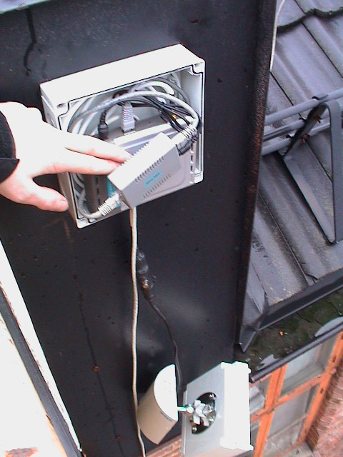 |
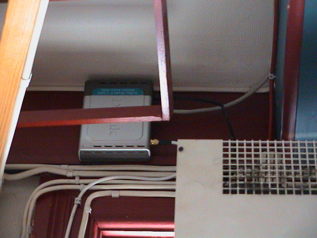
| Successfully installed . | Power-over-ethernet adaptor in the front and the access point in the back. | Antenna haning down while installing the box. |
 |
 |
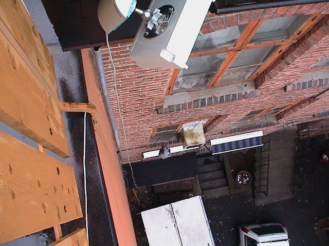
 |
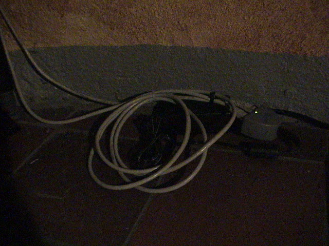
| It's pretty far down to the first floor, around 10 meters. | Another view of the cabling. | I could have turned the AP around to avoid any water to enter the connections. |
 |
 |
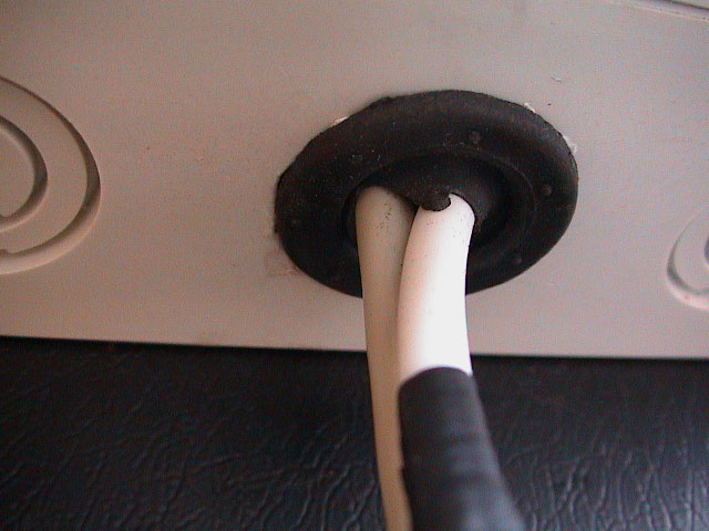 |
| The ethernet cable is twisted around the steel foot to avoid stress on the AP, strips should have been used instead. | The surge protector is still hanging down since it's not the highest point of the building. | Both the ethernet and coax cable is fed through a single hole protected by membrane grommet. |
 |
 |
 |
| You can see site A just right of the center in this picture. | Everything is ready to rock. | The other PoE terminator on the first floor. |
I chose sector antennas because they provided decent gain, 8.5 dBi, and had a beamwidth that covered the area well. Also by using sector antenna I could hook up a possible third node later that's within the beamwidth of site A if necessary. A third node should not be a problem since the first two nodes isn't that far apart and power output loss of a third node shouldn't affect the overall performance.
If only two nodes should be connected together, a more directional antenna would make the signal more stronger and the noise level lower. But directional antennas usually costs more and homebrew made stuff needs serious weather protection before it's installed outside.
The D-Link antennas came with a N female connector, a lightning surge protector and a N male to RP-SMA male 3 meters extension cable.
Radioation pattern:
The access points are setup to create a simontanous network bridge between two locations, just like a wired network would do. No fancy DHCP server, MAC filters or SSID broadcasting settings necessary, just strip down the setting to create a resonable secure wireless bridge between two access points. Luckly the DWL-2000AP access point provided exactly that.
Setting the "Wireless Bridge: Remote Bridge MAC" under "Advanced" to the MAC address of the other access point brings up a link only between those two access points.
To make sure noone else easily can sniff data flying over the airwaves, encrypting it with 128-bit WEP encryption is a decent way to protect against bypassing wardrivers. It can be enabled under "Home", "Wireless" and then "WEP Encryption".
Super-G is a marketing phrase used by D-Link to describe the method used to pair up frequency channels to enhance the throughtput and performance of network. This was introduced in a firmware released after the access point were announced, only revisions B and C of the AP is Super-G supported. It can be turned on under "Advanced", "Performance" and then "Super G". Using "Super G with Static Turbo" seems to be the most reliable setting.
The connectors between the antenna, surge protector and extension cable was tightly sealed with electical tape to prevent water entering the connection.
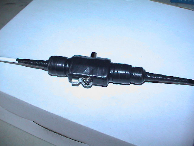 |
 |
 |
| The surge connection is heavily protected with electical tape. Non-UV resistant though. | Additional protection at the antenna end. | Complete antenna setup, extension calbe, surge protector and the antenna. |
The box is rated as weatherproof and is constructed with a rubber gasket around the edge of the enclosure cover. The holes on the bottom are sealed with rubber membranes for the antenna coax and the ethernet cable. To let condense out the seals are not 100% tight.
As regarding with temperature, I've not installed any heaters or ventilation holes. D-Link has rated the AP's operational temperatures to 0 - 55 degree celsius (32 - 149 degree farenheit). I don't know how the AP will behave in a sub-zero environment, but I'll monitor the AP throughout the upcoming winter here in Norway. Anyway, I won't be suprised if it breaks and malfunctions as it's not really über-expensive quality stuff, just regular consumer products you can buy anywhere.
The IP network I've configured is more advanced than a regular home setup. A gateway is located on each side of the link providing proper routing and firewall rules for the respective networks connected to each site.
I won't go in to the setup in detail here.
Both latency and throughput wise the link is performing perfect. But in the beginning I had problems that the link would drop if no traffic were transferred in a prolong amount of time. I kinda 'fixed' this by setting up a latency statistic graph (MRTG) polling the other side of link every 5 minutes.
Since the access point is not providing any noise or signal levels, I can't figure out how strong the signal strength is.
| Site A to Site B
user@sitea:~$ ping -c 10 siteb Site B to Site A user@siteb:~$ ping -c 10 sitea |
About 25 Mbit/s.
<to do, add advanced bw measure>
Atheros Wireless LAN Drivers [phoenixnetworks.net]